How To Succeed In Writing Isometric Projection Assignments
What are the three basic axes of isometric projection?
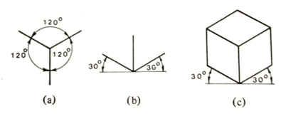
Fig. 4.9 Isometric axes
Figure 4.9(c) shows a cube drawn in isometric projection - the edges receding to the right and the left is parallel to the isometric axes.
Discuss in detail drawing in isometric projection
A pictorial view of an object can be produced in isometric projection using drawing instruments. To overcome the effect of the receding lines appearing to be slightly larger than the actual size, a reduced or isometric scale can be used, where receding lines are about 0.8 of the true lengths, Fig. 4.16. In practice, however, little use is made of this scale.
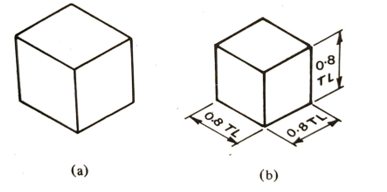
Fig. 4.16 (a) All actual true lengths, (b) Foreshortened receding lines
To draw an isometric circle using ordinates (Fig. 4.17)
- Draw a circle as a plane figure, with center lines inscribed in a square. Divide the circle by an even number of equidistant ordinates.
- Draw the required 'isometric square' with all sides equal and add centre lines.
- Transfer all ordinates from the plane-circle drawing to the 'isometric square' along the center line AB, with corresponding ordinate measurements above and below AB.
- Join the plotted points with a uniform bold line, preferably using a French curve to complete the ellipse.
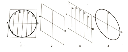
Fig. 4.17 Drawing an isometric circle
This system of transferring ordinates from plane figures to isometric views may be used for any regular or irregular shape. Figure 4.18 shows irregular shapes in isometric projection, where ordinates representing the uniform thickness of the object are of the same length and are measured along the isometric axes.
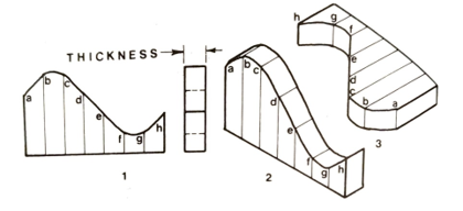
Fig. 4.18 Irregular shapes in isometric projection
What is the procedure of constructing isometric circles using instruments?
- Draw an 'isometric square' ABCD, each side being equal, and then draw a long diagonal DB bisecting the two acute angles D and B (Fig. 4.19).
- Join the mid-points of each side to the opposite obtuse angles A and C.
- Use the intersection points E and F on the diagonal as the centers to draw two small arcs between the nearest mid-points.
- With centers at A and C, draw the remaining arcs between the mid-points.
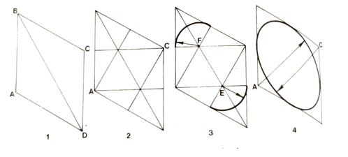
Fig. 4.19 Construction of a circle in isometric projection
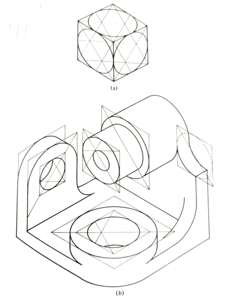
Fig. 4.20 Isometric circles in three planes: (a) all construction lines are shown, (b) some construction lines were omitted for clarity