Guidance To Writing An Architecture Assignment On Sketching
What is pictorial Projection?
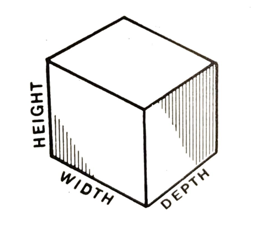
Fig. 4.1 Representation of a three-dimensional object
Why is perspective projection an essential concept in freehand drawing?
Appreciation of perspective is essential for learning the fundamentals of freehand sketching. Objects at a distance appear to be smaller than those which are near. Two parallel lines representing the edges of a straight road seem to come closer together and then meet at a point on the horizon. That point is called the vanishing point (VP), Fig. 4.2.
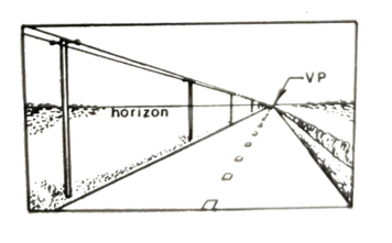
Fig. 4.2 Perspective projection
Perspective projection involves several receding lines called projectors converging at two or more vanishing points. The objects sketched are then presented as they would appear when observed from a particular point in real life.
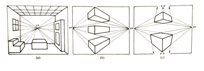
Fig. 4.3 (a) One-point, (b) two-point, and (c) three-point perspective
In Fig. 4.3(a), a one-point perspective is shown, where one of the principal faces is parallel to the picture plane.
In Fig. 4.3(b), perspective is shown, where all principal faces are inclined. This method is commonly used for industrial sketching.
In Fig. 4.3(c), a three-point perspective is shown, where one vanishing point is outside the picture frame.
For engineering purposes, when sketching small objects, the vanishing points are considered to be placed outside the frame of the drawing paper. This is because such objects are usually viewed from a Close distance.
In Fig. 4.4, the features of the objects above the eye-line or horizon are seen from below, and the features below the horizon are seen from above.
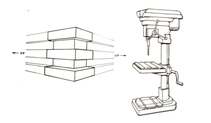
Fig. 4.4 Objects drawn in perspective projection
For guided perspective sketching, use the grid in Fig. 4.8 Place tracing paper over the grid and sketch the objects required using the projectors. Alternatively, draw your projectors radiating from two vanishing points on the horizon.
Figure 4.5 shows a block with several holes and protruding cylinders drawn in perspective projection. The perspective grid was used for this guided drawing. Note how all axes, block edges, and sides of cylinders either are vertical or converge towards the two vanishing points on the horizon.
All ellipses representing circles were drawn at 90° to the corresponding longitudinal axes or center lines. (All 90° angles on the drawing are represented by small squares).
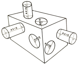
Fig. 4.5 Circular shapes in perspective projection
How do you sketch an ellipse representing a circle?
- Sketch an enclosing 'isometric square', i.c. a rhombus, with its sides equal to the diameter of the circle under consideration.
- Sketch bisecting lines and, at the intersection points, sketch short tangential arcs.
- Finish the ellipse with a uniform bold line.
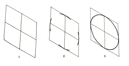
Fig. 4.10 Sketching a circle
What is the alternative quick method of sketching ellipses?
- Sketch a faint construction line AB representing the longitudinal center of a hole or cylinder.
- Sketch the major axis CD of the required ellipse at 90° to the longitudinal centre line.
- Sketch the ellipse, estimating the minor axis.
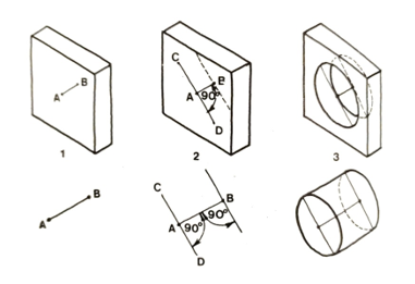
Fig. 4.11 Sketching circular shapes
Figure 4.12(a) shows holes sketched in three planes. Figure 4.12(b) shows cylinders sketched in three planes.
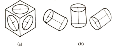
Fig. 4.12 Holes and cylinders sketched in three planes
To sketch cylindrical objects, first, draw the complete construction ellipses, then draw tangential blending lines as shown in Fig. 4.13.
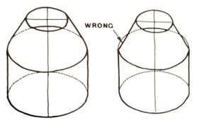
Fig. 4.13 Cylindrical objects
What are the steps of sketching a nut?
- Sketch three vertical construction lines, placed at D and D/2 apart, where dimension D represents a nominal (major) thread diameter. Then sketch a hexagonal prism of height D, using the three vertical construction lines with all receding sides sloping at 45°.
- Sketch lines parallel to the edges AB, BC, and CD at a distance of D/5 from them, and sketch three arcs between these construction lines.
- Sketch a horizontal tangential ellipse in the upper hexagon, representing the chamfer circle.
- Sketch two blending arcs and include the threaded hole, which should be slightly smaller than D in diameter. Finish the sketch with uniform bold lines. The threaded hole would be represented by equispaced parallel sections of ellipses.
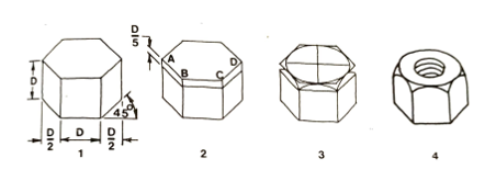
Fig. 4.14 Sketching a nut
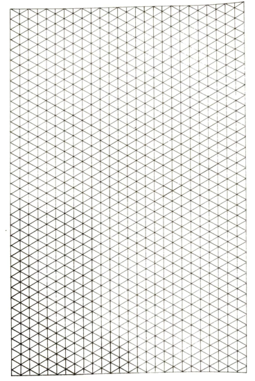
Fig. 4.15 Isometric grid for guided sketching