How To Tackle Oblique Projection Assignment Questions With Ease
What is an oblique projection?
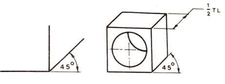
Fig. 4.23 Basic oblique axes and 'cabinet' projection
All proportions and measurements can be made only along these three axes.
A comparison of three pictorial projections is shown in Fig. 4.24.
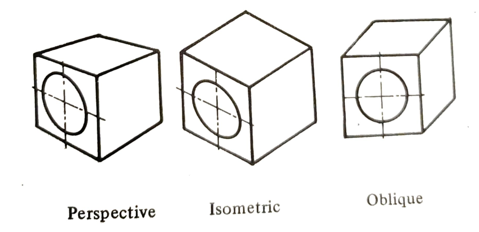
Fig. 4.24 Pictorial projections
How do you draw an oblique projection?
The main advantage of oblique projection over isometric is that any complicated face - which may be curved, irregular, or has several holes can be drawn as its true shape using drawing instruments.
The receding surfaces can be drawn at any angle but are usually drawn at 45 and are foreshortened to half-true length.
All receding surfaces shown in Fig. 4.25 are half true length but at different angles.
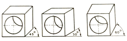
Fig. 4.25 Receding surfaces at different angles
In Fig. 4.26 the required semicircles are drawn with centers at A. B and C are positioned along a line at 45" and distances of half-true lengths.
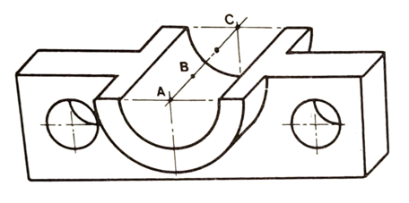
Fig. 4.26 Bracket in oblique projection
Figure 4.27 indicates the advantages of oblique projection when drawing a complicated cylindrical component.
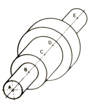
Fig. 4.27 Cylindrical component in oblique projection
What are the steps of drawing cylindrical shapes in oblique projection?
- Draw the axis of the cylindrical shape at 45" to the horizontal and locate the points A, B, C, and D representing all normal (at 90") surfaces along the axis at distances of half true length.
- Draw the required construction circles at the points A, B, C, and D.
- Join adjacent pairs of same-size circles by tangents at 45°.
- To complete, draw all circles and blend tangents with uniform bold lines as shown.
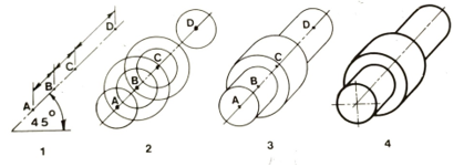
Fig. 4.28 Drawing cylindrical shapes
Figure 4.29 shows how complicated cylindrical shapes can be represented in oblique projection.
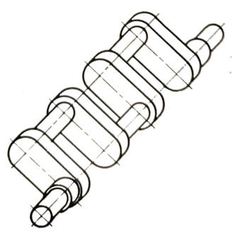
Fig. 4.29 Crankshaft in oblique projection
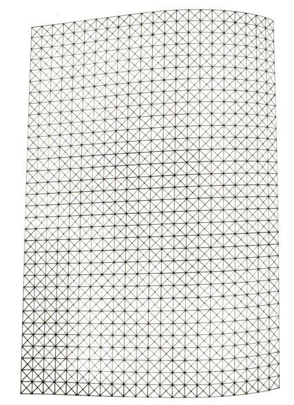
Fig. 4.30 Oblique grid for guided sketching