How To Crack An Advanced Loci Assignment: Tips & Strategies
- Conduct extensive research on the questions
- Carefully read and understand the questions before answering
- Brainstorm with your classmates
- Revise the solutions before submitting the assignment
- Get feedback from your instructor
Question 1: What is a cycloid in loci and how can it be drawn?
Answer: A cycloid is the locus of a point on the circumference of a circle which rolls without slipping along a fixed straight line.
When a disc with a pencil positioned on its periphery is rolled along a straight edge without slip, the moving pencil will trace the cycloid curve.
The profile of certain gear teeth is based on the cycloid curve.
To draw a cycloid:
- Draw a circle of radius R, say, with centre O and mark off, say, twelve points equally spaced around its circumference as shown in Fig. 15.6. Number the points in a clockwise direction, the bottom point being numbered twice (0 and 12).
- Through each point draw a horizontal construction line.
- On the construction line passing through O, mark out a distance equal to the circumference of the circle (2R) and divide it into twelve equal parts with points O, O1,..., O12.
- From centre O, strike an arc of radius R to intersect the construction line from O on the circumference. Call the intersection point Po.
- From centre O1, strike another arc of radius R to give point P where it intersects the construction line from me on the circumference.
- From centres O2, O3,..., O12, strike arcs in the same way to give points P2, P3, ..., P12.
- Join points Po to P12 by a smooth curve. The resulting locus is the cycloid.
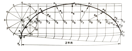
Fig. 15.6 Cycloid
Question 2: Differentiate an epicycloid from a hypocycloid
Answer: An epicycloid is the locus of a point on the circumference of a circle which rolls without slipping along the outside of a fixed base circle. A hypocycloid is the locus of a point on the circumference of a circle which rolls without slipping along the inside of a fixed base circle.
The profile of certain gear teeth is based on a combination of epicycloid and hypocycloid curves, as shown in Fig. 15.7(b).
To draw an epicycloid or hypocycloid (Fig. 15.7(a)):
- Strike an arc of the appropriate radius for the fixed base circle and draw the rolling circle of radius R touching it - above the arc for the epicycloid, below it for the hypocycloid.
- Mark off, say, twelve equally spaced points around the circumference of the rolling circle and number them as shown- clockwise for the epicycloid, anticlockwise for the hypocycloid.
- With centres at the centre of the fixed base circle, draw construction arcs through these points and the centre of the circle, O.
- Along the arc of the fixed base circle, mark off a length equal to the circumference of the rolling circle (2R). This length subtends an angle = R/Rbx 360 at the centre of the base-circle arc.
- Divide this angle @ into twelve equal parts by lines passing through the construction arcs. On the construction arc passing through the centre of the rolling circle, O, number the intersection points O1, O2…. O12 as shown.
- From centre O1, strike an arc of radius R (rolling-circle radius) to give point P, where it intersects the construction arc passing through point 1 on the rolling circle.
- From centre O2, strike another arc of radius R to give point P2 where it intersects the construction passing through point 2 on the rolling circle.
- From points O, 03, 04, ..., O12, strike arcs in the same way to give points Po. P3, P4, P12.
- Join points Po to P12 by a smooth curve. The resulting locus will be the epicycloid or hypocycloid as appropriate.
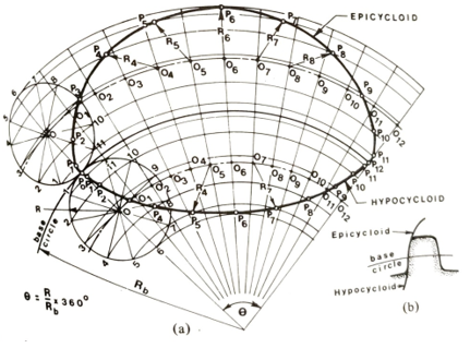
Fig. 15.7 Epicycloid and hypocycloid
Question 3: Discuss the steps of drawing an involute
Answer: An involute is the locus of a point on a straight line that rolls without slip around a circle.
If a length of string with a pencil attached to its free end is unwound under tension from around the circumference of a fixed disc, then the moving pencil will trace an involute curve. Part of the involute curve is used for gear-tooth profiles, as shown in Fig. 15.8(b); it has many advantages over the cycloid curves.
To draw an involute:
- Draw the base circle and mark off, say, twelve equally spaced points around its circumference, numbering the points as shown in Fig. 15.8(a).
- At point 1, draw a tangent of length equal to one-twelfth of the circumference of the circle. The 'free' end of the tangent is point P1.
- At point 2, draw a tangent of length equal to two-twelfths of the circumference of the circle, to give point P2.
- In the same way, from points 3, 4,..., and 12 draw tangents of length 3/12, 4/12,..., and 12/12 of the circumference of the circle respectively. to give points P3, P4,..., P12.
- With the aid of a French curve, join points P, to P2 by a smooth curve. The resulting locus will be the involute.
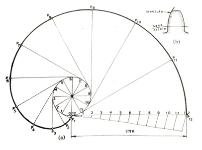
Fig. 15.8 Involute
Question 4: Explain why it is important to consider the loci of the various points on a mechanism during design
Answer: A mechanism is a machine or part of a machine consisting of a system of moving parts. Any rigid piece of the mechanism pivoted at the ends is called a link. Arrangements of links, pivots, and slides are often used to convert circular motion into reciprocating or oscillating motion, and vice versa.
When designing a mechanism to perform a specific task, the loci of various points on the mechanism must be drawn to determine the velocities, accelerations, and forces involved in the motion produced. It is also necessary to study the movements of the links so that clearances may be checked and safety guards or shields may be designed to protect the users of the machine.
Question 5: Discuss the two common types of mechanisms
Answer: Two very common types of mechanisms are the slider crank and the four-bar chain.
Slider-crank mechanism
The slider-crank is a simple mechanism in which rotary motion is converted to linear motion or vice versa. Figure 15.9(a) shows a crank AB which rotates about A and is joined by the connecting rod BC to the piston (slider) C which slides along the axis AC.
To plot the locus of a point P on the mechanism (Fig. 15.9(b)):
- Draw a circle of radius equal to the crank length AB and mark off, say, twelve points equally spaced on its circumference as shown. Number the points B1, B2,..., B12.
- Draw the axis AC through the centre of the circle and the slider and, with a radius equal to the length of the connecting rod BC, strike arcs from B1, B2, ..., B12 to intersect AC at C1, C2, ..., C12.
- Join B1,C1, B2C2. B12C12 to give the positions of the connecting rod BC for twelve different positions of the crank AB.
- With the same centres, B1, B2, ..., B12 and radius BP, strike arcs to intersect BiC1, B2C2, B12C12 at P1, P2, ..., P12.
- Join points P1, P2,..., Piz by a smooth curve. This is the locus of the point
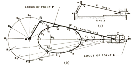
Fig. 15.9 Slider-crank mechanism
Alternatively, a trammel method may be used. The trammel, which may be a piece of paper with a straight edge on which the relevant points are marked, represents the connecting rod and its movements are plotted. The trammel method enables a large number of points to be obtained quickly, and so is widely used by designers in the industry. To plot the locus of a point P on the mechanism using a trammel:
- On an axis AC with centre A, draw a circle of radius equal to the crank length AB.
- Mark points BPC on the edge of the paper to represent the connecting rod.
- Place the paper in various positions such that point B always touches the circumference of the circle and point C is always on the axis AC. For each position, mark the position of P.
- Join the successive positions of P to obtain the required locus.
Four-bar chain
The four-bar chain is a simple mechanism which consists of two cranks, AB and CD, joined by a rod BC. The fourth link is between the two fixed pivots A and D, as shown in Fig. 15.10(a).
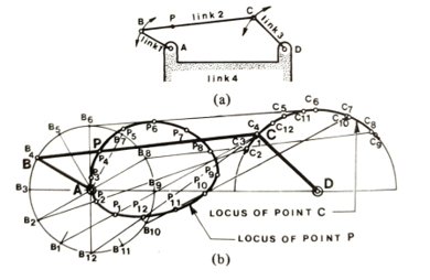
Fig. 15.10 Four-bar-chain mechanism
To plot the locus of a point P (Fig. 15.10(b)):
- Draw a circle of radius AB with centre A and another of radius DC with centre D.
- Mark off, say, twelve equally spaced points on the circle of radius AB to correspond to twelve different positions of the crank AB. Number the points B1, B2..., B12 as shown.
- With B1, B2, and B12 as centres, strike arcs of radius equal to the length of the connecting rod BC to intersect the circumference of the circle of radius DC at points C1, C2, ..., C12.
- Join B1, C1, B2C2, and B12C12 to give the positions of the connecting rod BC for twelve different positions of the crank AB.
- Again with centres, B1, B2, ..., B12, strike arcs of radius BP to intersect B1C1, B12C12, at P1, P2, ….,P12.
- Join points Pi to P12 by a smooth curve. This is the locus of point P. Alternatively, a trammel method may be used.
Question 6: Explain the working principle of a sliding link
Answer: If a ladder AB is propped against a wall and the bottom end slides outwards from B to B2, then the top of the ladder will slip correspondingly from A to A2, since the length of the ladder remains constant.
A sliding link is free to move in one plane such that one end of the link is always in contact with a line OY and the other end is always in contact with another line OX.
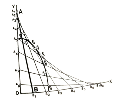
Fig. 15.11 Sliding link
To plot the locus of a point P on the link (Fig. 15.11):
With centres A1, A2,..., etc. on line OY and a radius equal to the length of the link AB, strike several arcs to intersect OX at B1, B2,..., etc.
Join A1B1, A2B2, ..., etc. to obtain various positions of the link.
Again with centres A. A2...., etc., strike arcs of radius AP to intersect A, B, A2B2...., etc., at Pr. P, etc.
Join the points P1, P2,..., etc, with a smooth curve. This is the required locus.
Question 7: How does a quick-return mechanism reduce the time wasted during non-cutting return stroke of a shaping machine?
Answer: The quick-return mechanism shown in Fig. 15.12 is used to reduce the time wasted during the non-cutting return stroke of a shaping machine, etc.
A pinion drives a gear wheel with a uniform angular velocity. Attached to the gear wheel is a pin which rotates with it and at the same time moves a sliding block up and down inside the slotted link, which in turn oscillates about its pivot. The shaping-machine ram, which is joined to the top of the slotted link by means of a connecting link, makes its cutting stroke while the pin is travelling through the larger arc, of about 240°. The non-cutting return stroke is made while the pin travels through the smaller arc, of about 120°. Thus the ram moves back twice as fast as it moves forward on its cutting stroke.
The length of the ram stroke can be adjusted by changing the radial distance of the pin from the centre of the gear wheel.
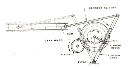
Fig. 15.12 Quick-return mechanism